Autor of Rolling3 program:
A.Milenin
Publications:
Program base describe:
1. Миленин А.А. Исследование с помощью математической модели процесса уширения при прокатке металлов с разными реологическими свойствами // Изв. РАН. Металлы. – 1998. – №4.
– С. 48–51. (Milenin A.
MATHEMATICAL MODELING OF THE SPREAD OF METALS WITH DIFFERENT RHEOLOGICAL
PROPERTIES ON ROLLING, Russian metallurgy. Metally, ISSN 0036-0295 1998, No4, pp. 65-68 //
Allerton Press,
2.
Миленин А.А.
Исследование
численных
свойств
алгоритмов
метода конечных
элементов
применительно
к трехмерным
задачам
обработки
металлов
давлением // Изв.
РАН. Металлы. – 1998.– №5.–
С. 33–37 (Milenin A.A. NUMERICAL PROPERTIES OF FINITE-ELEMENT ALGORITHMS
IN THE THREE-DIMENSIONALSHAPING OF METALS, Russian metallurgy. Metally ISSN 0036-0295, 1998, no5, pp. 38-43,
Publisher: Allerton Press,
Application of program Rolling3d to shape
rolling technology:
The FEM model of rolling
processes:
To create a numerical model with the
capability to simulate cyclic horizontal movement of rolls the major
modification to the in-house Rolling3d code are introduced. The main principles
of the FE code are described in [1,2]. Examples of possible applications of the
Rolling3d code to solve different problems in development of a rolling shape
technology are published in [3-5]. Main principles of the developed FE code are
gathered below.
The theory of the non-isothermal
plastic flow of incompressible non-linear viscous medium is applied to solve
the problem. Boundary conditions are taken into account by the method proposed
in [1]. The essential idea of this method involves application of the penalty
function to reckon metal-tools interaction in complex spatial configuration.
Solution is sought from the stationary condition of the modified Markov functional:
![]() , (1)
, (1)
where:
 , (2)
, (2)
![]() , (3)
, (3)
where: р –
iteration number; vt - metal slip
velocity with respect to the tool (m/s), vn – metal velocity
normal to the tool surface (m/s), wn - normal component of the velocity
of the tool surface (m/s), t - friction stress
(according to the law t=mss, where m –
friction factor), ss – yield stress
(MPa), s – mean stress
(MPa), ![]() – effective strain
rate (s-1),
– effective strain
rate (s-1), ![]() – strain rate in the triaxial compression test (s-1),
Kt – the penalty
coefficient accounting for the metal slip velocity over the tool computed based
on the data from the previous iteration (p-1), Kn – the
penalty coefficient for the metal penetration into the tool, m – effective metal
viscosity computed from (3) by the method of hydrodynamic approaches (MPa s), V
– volume (m3), F – contact
surface (m2).
– strain rate in the triaxial compression test (s-1),
Kt – the penalty
coefficient accounting for the metal slip velocity over the tool computed based
on the data from the previous iteration (p-1), Kn – the
penalty coefficient for the metal penetration into the tool, m – effective metal
viscosity computed from (3) by the method of hydrodynamic approaches (MPa s), V
– volume (m3), F – contact
surface (m2).
If the penalty
coefficient Kt increases, the
metal slip over the contact surface is hampered. Kt = 0
corresponds to frictionless metal slip.
In the present model the friction
anisotropy is introduced. It provides a possibility to transfer the horizontal
movement of rolls into the material without usage of the grooved rolls. Major
assumptions of this approach have already been explained.
The full tangential slip metal
velocity over the tool is a sum of the two components:
![]() (4)
(4)
where 1 an 2 are axes
of the local coordinate system in a current contact point in directions tangential
to the contact surface. The local axis marked as
Therefore, the friction
part of (1) is described as:
![]() , (5)
, (5)
where:
![]() , (6)
, (6)
![]() , (7)
, (7)
where m1 and m2 are friction factors in directions 1 and 2,
respectively.
The horizontal velocity of
rolls (in direction Y) is accounted for
during the simulation by implementation of the following function:
 (8)
(8)
where: ![]() - time of roll
movement in direction Y during one
oscillation,
- time of roll
movement in direction Y during one
oscillation, ![]() - rolling time,
- rolling time, ![]() - movement amplitude
in direction Y.
- movement amplitude
in direction Y.
The phenomena of
contact loss between rolls and the sample during horizontal movement of rolls
is observed experimentally (figure 4) and has to be taken into account in the
proposed model. This
is done by an additional boundary condition:
![]() ,
,
where ![]() is a normal stress calculated
in current point at the contact surface.
is a normal stress calculated
in current point at the contact surface.
The model developed in
the present project is capable to transfer additional horizontal movement of
rolls to the material not via the grooved rolls, but via anisotropic friction
conditions. This significantly reduces computational time. Another important issue
that has to be considered is temperature change during the MEFASS rolling [5].
Deformation heating is extremely important as it is one of the mechanisms
leading to load reduction. In order to simulate temperature changes, the following
heat transfer equation is solved:
![]() , (9)
, (9)
where: r (t)- metal density (kg/m3), t – temperature (K), t - time
(s), k(t) – heat conductivity coefficient (W/m K), ceff(t) - effective
specific heat (J/kg K), ![]() .
.
The 3D solution of the temperature
field distribution along the sample is built upon the subsequent solutions of
the plane tasks, which correspond to the location of the sample cross-section
during rolling. To solve equation (9) the variational problem formulation that
is based on the minimization of the functional J is applied:
 (10)
(10)
where: a – coefficient of heat exchange, (W/m2 K),
t¥ -
temperature of air or roll (K).
Finally
the temperature derivative with respect to time is calculated implicit by
equation:
![]() . (11)
. (11)
Possibilities of Rolling3 software:
Optimization
of metal forming during rolling in the grooves of complex shape by mathematical
model (Fig. 1):
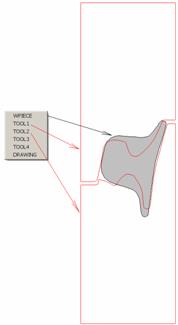
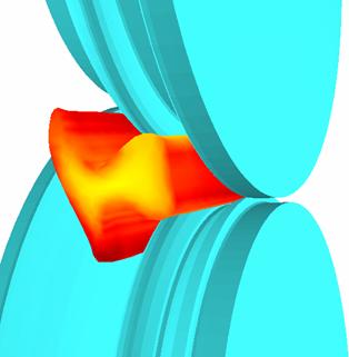
Fig. 1. Modelling
of rail rolling
Numerical
modeling of stock stability in the shape grooves [4].
Optimization
of temperature distribution in profile.
The rolls
temperature change.
The rolls
wear prognoses (Fig. 2).
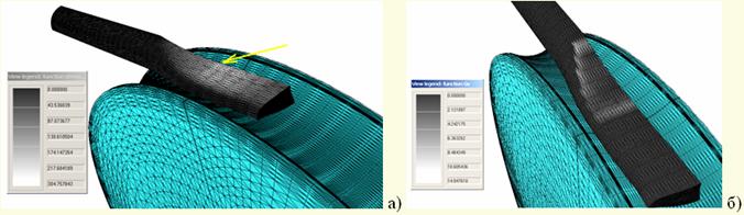
Fig. 2. The
wear parameter distribution on contact surface (a), the velocity of sliding
distribution on contact surface (b).