Computer - Aided Analysis of Dynamics of Belt Conveyor
With Automatic Follow-Up Device Stretching the Belt
 

Roman Jablonski Prof. Ph.D.Eng.
Piotr Kulinowski Ph.D.Eng.
University of Mining and Metallurgy, Cracow, Poland
Department of Mining Machines and Waste Utilization Equipment

Belt conveyors, tension systems, simulation tests
 

Abstract

The paper deals with the dynamics of the belt conveyor with the mechanical automatic follow-up device stretching the belt by two stretching cars in the loop unit.
The mathematical, discrete model of the belt conveyor is used for analysis of this system. In the analysis, the belt is substituted by the rheological model describing dynamic properties and the Rayleigh model as a multi-mass discrete representation of the belt continuity.
The system of differential equations describing the belt conveyor model is given as a multivariate computer program.
The calculation results gave the following information: about the tension variations in the belt, acceleration, velocity of chosen points of the belt and displacements of stretching cars. Starting and stopping of the belt conveyor have been considered.
Simulation tests have been experimentally verified on the real object. It was the underground coal-mine belt conveyor (length: 910 m, power 2x150 kW). Authors used the TV-camera to register a displacement of the stretching car during starting of the conveyor. Results of simulations and experiments were compared and show the satisfactory similarity.

1. Introduction

Correctness of the project of belt conveyor depends on selection of three mutually dependent elements: belt, drive and tension system. Efficient selection of parameters of these elements can guarantee long-lasting, defect-free work of the conveyor belt. The expenses of the conveyor belt amounts about 50% of conveyor capital costs.
Designers use the standard methods for calculations operating parameters of the belt conveyors, but these analyses gives the unsatisfying results during starting and stopping of conveyors. In mining belt conveyors are used modern types of drives: "soft-start", intermediate belt drives (T-T systems), new construction of belt cord, new types of tension systems and horizontal curves. Therefore designers should to dispose of calculating methods in order to identify technical effects of usage specific drive type, tension system and conveyor belt with specific viscoelastic properties.

2. Dynamic discrete model of the belt conveyor

Analysis of the dynamic phenomena in belt conveyors during starting and stopping can be done with simulation tests of the discrete belt conveyor model. In this model, the belt is substituted by the viscoelastic model describing dynamic properties and the Rayleigh model as a multi-mass discrete representation of the belt continuity.
Discrete belt conveyor models have been used for analysis of dynamic phenomena during starting and stopping since the 70’s and were described in [1, 5, 6, 8, 10, 12, 14].
    Fig.1. Discrete model of the belt conveyor
     
The calculating method, supported by dynamic discrete model of conveyor, make possible to record tensions, accelerations, velocities and movements in chosen points located on the conveyor, during starting, stopping and the other conditions of the conveyors operating.
The tested conveyor may have optional layout and can be loaded at any point along the conveying route. Also it can be equipped with many kinds of drive types and tension systems.
In simulation tests of drives were taken into consideration: motors, hydraulic and flexible couplings, brakes, reducers and possibility the belt slip on the drive pulley.
For calculating the frictional resistance of belt conveyor was used the computer program QNK supported by the DIN22101.
The discrete model of the belt conveyor makes possible to model all known tension systems: fixed, gravity take-up, winch operated, pneumatic take-up, hydraulic take-up and mechanical follow-up device.

3. Comparison of simulation tests and measurement results of selected parameters of operating of automatic follow-up conveyor tension system in belt conveyor JANINA/PIOMA 1000

The belt conveyor JANINA/PIOMA 1000 is located in the polish underground coal-mine "Janina". This belt conveyor is equipped with the Mechanical Follow-up Belt Tension (MFBT) system with two trolleys in the loop unit. [3]
Fig.2. Layout of the investigated belt conveyor JANINA/PIOMA 1000

The principle of MFBT operation shows the scheme on Fig.3. The task of this tension system is to keep forces T1 and T2 in constant proportion (T1/T2 = constant = b/a) and to eliminate the belt slip on the drive pulley.

Fig.3. Diagram describing operating of the mechanical follow-up tension system
with two stretching drums

In belt conveyor drums are located on trolleys linked with rope. Its transmission ratio depends on the type of drive (friction factor between belt and the drum pulley surface, angle of wrap). The first trolley "A" is located in the area of belt running on the drive drum (red color on figures), the second one "B" in the area of belt running off the drive drum (green color on figures). (Fig.4, Fig.5)

Fig.4. Mechanical Follow-up Belt Tension (MFBT) system with two trolleys in the loop unit
Fig.5. Trolley "A" in the model of the belt conveyor with MFBT system
Fig.6. Measurement of the movement of the trolley "A"
 
At the start-up both trolleys are in their extreme right position, the drive drum is pulling the top run of the belt inducting an increasing force T1. That force appears on both sides of the drum of the first tension trolley. Therefore this trolley is pulled by a force equal 2 x T1. The movement of this trolley (through a set of pulleys and a rope) causes movement of the second trolley. And the entire system is tensioned automatically by its own tension force T1.
The analysis of courses of forces variations in the belt, velocities and trolleys movements permits to find relations between the velocity of stress front in the belt and the movement of trolley stretching the belt in the starting conveyor. Those relations as results of simulation tests are presented on fig.7, fig.8, and fig.9 (red line).
Fig.7. Courses of force variations in the belt running on and off the drive drum
(computer simulation) – empty conveyor
 
Fig.8. Belt velocities on the drive and tail pulley (computer simulation) – empty conveyor
 
Fig.9. Movement of the trolley “A” in MFBT system – empty conveyor
Red line – computer simulation
Green line – measurement

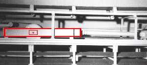
The tension device described above will to exactly follow-up system if both trolleys have possibility to move. If the trolley "A" will lean against the buffer (extreme right position) then this device will be "fixed" - T1/T2 is not constant.
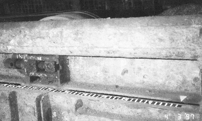
For the verification of simulation tests authors used the TV-camera to register a movement of the stretching trolley "A" during starting of the empty conveyor (Fig.6). The result of measurement is shown on fig.9 (green line).
The results of simulation tests are presented by using the computer program DynaBelt.

Fig.11. Dynamic diagram of tension in conveyor belt and animated operating of trolleys
in MFBT system
Fig.12. Courses of tension variations in the belt for chosen points located on the conveyor

Download  the compressed computer program dynabelt.zip (292 K).
 

4. Summary and conclusions

5. References

Roman Jablonski Prof. Ph.D.Eng.
Piotr Kulinowski Ph.D.Eng.
University of Mining and Metallurgy, Cracow, Poland
Department of Mining Machines and Waste Utilization Equipment
Al. Mickiewicza 30, B-2, pok.6
tel. +48 12 173074
fax +48 12 335162
e-mail kulipi@uci.agh.edu.pl