As an example a simple set of rules is chosen. Here are the rules the expert system should be based on. There are three attributes: a, b and valve. There is also an action defined as a variable called status. The process of developing the rules using the Osiris is shown in Figures: 6.9, 6.10, 6.11 and 6.12. The rules follow:
The following steps should be performed.
Start the Osiris system invoking:
osiris
The Edit button should be clicked, then the Editor appears. To
create an object which represents the decision table given in Table
6.2, press the create button (switching to the
create mode), then click inside the workspace. The
Create window should appear (Fig 6.9). Set the number
of rows to 4 (there are four combinations) and the number of columns
to 2 (two attributes) and click OK to accomplish.
The properties window should appear. The appropriate cells of the spreadsheet-like widget should be fulfilled (see Fig 6.10). Then click the Apply button and the Close button then. Here it is a complete object which represents the decision table given in Table 6.2.
As the next object, another attribute object (valve) could be created. Click the workspace. Select 1 as the number of columns and 2 as the number of rows. Then, fulfill the object to represent the attribute called valve (it could be compared with two values: on or other). After this there are two graphical objects which represent a part of the rules. According to the rule number 6 objects should be connected with each other. So, press the left mouse button while the pointer is within the right connection area in the last row of the object number 0. Then drag to the left connection of the object number 1. The result should be similar to that given in Fig 6.11.
Then proceed to obtain the representation similar to that in Fig 6.12. Please note, that the order in which objects are created isn't important. The action objects could be created as the first ones as well.
The given example shows a simple logical structure. As a result there are two attribute objects (numbers: 0,1) and five action objects (numbers: 2,3,4,5,6) - see Fig 6.12.
This graphical structure can be expressed by five rules:
There are objects' numbers involved in the rule, in brackets
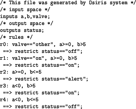
To generate a source file for Kheops just click on the Generate button of the Controller module. The source file named noname.k will be generated then (see Fig 6.13 for the generated code).
After that, the developed logical structure should be saved for future improvements, so the Save button could be used. The file, named noname.osiris will contain all the data, then. If the other filename is needed the menu ``File/Save As...'' should be used.
![\includegraphics[scale=0.8]{pic/ex1}](img44.png)
![\includegraphics[scale=0.8]{pic/ex2}](img45.png)
![\includegraphics[scale=0.8]{pic/ex3}](img46.png)
![\includegraphics[scale=0.8]{pic/ex4}](img47.png)